- Joined
- Sep 9, 2012
- Messages
- 410
- Location
- Germany, Wiedemar
- First name
- Joachim
Machinery:
Zetor 2011, Zetor 3045, Zetor 5011, Zetor 7340 Economic
Set injection timing - Zetor 50 Super
Now let's shed some light on the darkness. (Source: member @Dettl from zetor-forum.de)
The four-cylinder, four-stroke diesel engine from the Zetor 50 super rotates clockwise (clockwise) when viewed from the front on the V-belt pulley and makes two revolutions in order to let all cylinders run through all cycles once (intake/compression/combustion/ejection).
The ESP only makes one revolution, also to the right.
When you turn the engine twice, the setting mark on the flywheel appears twice.
However, the only interesting time is when the 1st piston in cylinder 1 is just before TDC and the first injection element begins to deliver diesel.
To adjust the pre-injection: (for the explanations, always only assume the 1st cylinder and its piston)
1. - Set the engine to start injection.
This means turning the engine until the 1st piston is just before TDC, the inlet and exhaust valves are closed (actually only visible when the valve cover is removed), and the 17° setting mark appears in the middle of the inspection hole in the clutch tunnel. Switch on and block decompression beforehand.
If possible, mark TDC on the front pulley beforehand.
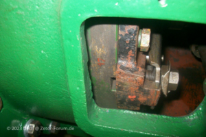
Setting marker in the middle of the inspection hole (visually slanted because the tie rod is in the way for straight photos)
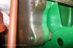
Matching marker on the engine housing in front of the clutch tunnel (marked zero with a line) Search!!!
2. - Check the ESP setting.
There is a mark on the circumference of the driven claw coupling half with an arrow attached to indicate the direction of rotation.
This marking should coincide with a marker on the front end shield of the ESP when injection begins.
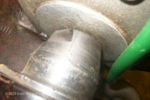
For you, Flachi, first remove the paint and look for the little arrow.
If there is no marking on the end shield (none of my two ESPs have it on it!) measure the width of the end shield and at least mark it in the middle above the shaft with a pencil.
Rotate both markings so that they are opaque.
The first injection element is now ready to start injection.
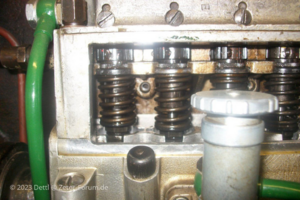
3. -Assemble the pump.
The pump is placed on the motor in the designated position, secured with the slotted screws, which are tightened evenly in a cross pattern and the lines connected when it was dismantled.
The engine should then run reasonably well after connection, bleeding and attempting to start.
However, this is only a provisional, casual setting so far and is used to set up the ESP on the engine.
Due to various circumstances such as steering wheels no longer brand new, camshaft a little worn, ESP not fresh, drives with bearing clearance and... and..., could the pre-injection in this situation is not 100% correct and the engine will not run optimally.
A lot of blah-blah so far, but in my opinion it is absolutely necessary for inexperienced mechanics to know.
4. -Check setting with capillary tube.
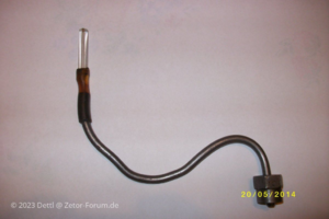
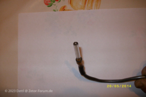
Homemade capillary tube from the GDR era
Dismantle the first injection line and replace it with a capillary tube.
With the ESP set to full delivery (full throttle), crank the engine until the capillary tube is filled with diesel without bubbles.
To do this, use an engine crank or (for the lazy people, including me! sst) just use the starter.
Now turn the engine as described under 1, only with the difference that the setting mark of the flywheel can only be seen at the top of the inspection hole in the clutch tunnel, i.e. the injection point has not yet been reached.
Now empty the fully fed tube slightly by blowing over it with compressed air or vacuuming it with a paper handkerchief so that the diesel level is 10 to 15mm in front of the mouth.
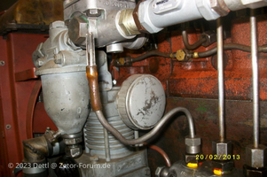
Diesel mirror about 15mm in front of the mouth
Using a small tool, tap the capillary tube a little to allow the last air bubbles to rise.
The diesel in the tube must be absolutely free of air, otherwise the result would be distorted.
Now allow the engine to continue turning in the direction of rotation, preferably with a helper, and carefully observe the diesel level in the tube.
If the diesel level begins to rise, stop immediately and read the setting marker on the flywheel.
The 17° marking should be in the middle of the inspection hole, at the marking on the engine side.
If the engine was turned too quickly or the rise in the diesel level was not correctly detected (which will happen in any case), do not turn the engine back for convenience, but turn the crankshaft forward another 4 revolutions and let the game play out again (overblowing, suction, knocking, Rotate, observe).
The RHB of the ZT 300 should be turned back (@Napi), but please don't do that! The result would be distorted!
Adjust, turn and read until the required setting is correct!
Only when the 17° marking is in the middle of the inspection hole of the coupling tunnel at the moment the diesel level rises would the setting be perfect.
However, this only applies to an engine that is in perfect working order.
However, if irregularities in the running of the engine, exhaust gas opacity and abnormal noises occur, the determined setting can be deviated slightly with appropriate experience and assessment.
Here, more due to wear, the pre-injection may be “slowing down”.
That's why the scaling from below on the claw clutch to the ESP, for me here 10 graduation lines, each with a longer one on the outside and one in the middle.
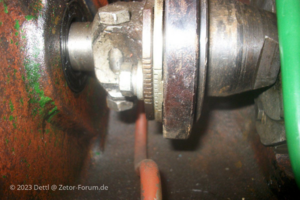
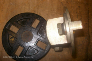
But exceptions prove the rule, here a new claw coupling with the associated original Pertinax disc with scaling at the top.
An adjustment from outer line to outer line of 6° on the KW can perhaps be assumed there.
If this attitude is to be fruitful, the following must be the case for me:
-not too worn out engine
- Diesel system intact and, above all, tight (feed pump and lines)
-new diesel filters
-new or at least tested, correctly adjusted injectors
-Tested ESP set according to manufacturer's instructions, with necessary, achievable injection pressure on the nozzles
There are other adjustment methods, for example with a drip tube. This or better not use any method that requires dismantling the pressure valve in the screw socket of the injection line connection.
According to Zetor and Motorpal , the sealing rings above the pressure valve are no longer available.
All photos without a date are current and taken from me (member @Dettl from zetor-forum.de) today, with my computer, so the setting is not rocket science and is easy. Of course, it can take some time!
Now let's shed some light on the darkness.
The four-cylinder, four-stroke diesel engine from the Zetor 50 super rotates clockwise (clockwise) when viewed from the front on the V-belt pulley and makes two revolutions in order to let all cylinders run through all cycles once (intake/compression/combustion/ejection).
The ESP only makes one revolution, also to the right.
When you turn the engine twice, the setting mark on the flywheel appears twice.
However, the only interesting time is when the 1st piston in cylinder 1 is just before TDC and the first injection element begins to deliver diesel.
To adjust the pre-injection: (for the explanations, always only assume the 1st cylinder and its piston)
1. - Set the engine to start injection.
This means turning the engine until the 1st piston is just before TDC, the inlet and exhaust valves are closed (actually only visible when the valve cover is removed), and the 17° setting mark appears in the middle of the inspection hole in the clutch tunnel. Switch on and block decompression beforehand.
If possible, mark TDC on the front pulley beforehand.

Setting marker in the middle of the inspection hole (visually slanted because the tie rod is in the way for straight photos)

Matching marker on the engine housing in front of the clutch tunnel (marked zero with a line) Search!!!
2. - Check the ESP setting.
There is a mark on the circumference of the driven claw coupling half with an arrow attached to indicate the direction of rotation.
This marking should coincide with a marker on the front end shield of the ESP when injection begins.

For you, Flachi, first remove the paint and look for the little arrow.
If there is no marking on the end shield (none of my two ESPs have it on it!) measure the width of the end shield and at least mark it in the middle above the shaft with a pencil.
Rotate both markings so that they are opaque.
The first injection element is now ready to start injection.

3. -Assemble the pump.
The pump is placed on the motor in the designated position, secured with the slotted screws, which are tightened evenly in a cross pattern and the lines connected when it was dismantled.
The engine should then run reasonably well after connection, bleeding and attempting to start.
However, this is only a provisional, casual setting so far and is used to set up the ESP on the engine.
Due to various circumstances such as steering wheels no longer brand new, camshaft a little worn, ESP not fresh, drives with bearing clearance and... and..., could the pre-injection in this situation is not 100% correct and the engine will not run optimally.
A lot of blah-blah so far, but in my opinion it is absolutely necessary for inexperienced mechanics to know.
4. -Check setting with capillary tube.


Homemade capillary tube from the GDR era
Dismantle the first injection line and replace it with a capillary tube.
With the ESP set to full delivery (full throttle), crank the engine until the capillary tube is filled with diesel without bubbles.
To do this, use an engine crank or (for the lazy people, including me!
Now turn the engine as described under 1, only with the difference that the setting mark of the flywheel can only be seen at the top of the inspection hole in the clutch tunnel, i.e. the injection point has not yet been reached.
Now empty the fully fed tube slightly by blowing over it with compressed air or vacuuming it with a paper handkerchief so that the diesel level is 10 to 15mm in front of the mouth.

Diesel mirror about 15mm in front of the mouth
Using a small tool, tap the capillary tube a little to allow the last air bubbles to rise.
The diesel in the tube must be absolutely free of air, otherwise the result would be distorted.
Now allow the engine to continue turning in the direction of rotation, preferably with a helper, and carefully observe the diesel level in the tube.
If the diesel level begins to rise, stop immediately and read the setting marker on the flywheel.
The 17° marking should be in the middle of the inspection hole, at the marking on the engine side.
If the engine was turned too quickly or the rise in the diesel level was not correctly detected (which will happen in any case), do not turn the engine back for convenience, but turn the crankshaft forward another 4 revolutions and let the game play out again (overblowing, suction, knocking, Rotate, observe).
The RHB of the ZT 300 should be turned back
Adjust, turn and read until the required setting is correct!
Only when the 17° marking is in the middle of the inspection hole of the coupling tunnel at the moment the diesel level rises would the setting be perfect.
However, this only applies to an engine that is in perfect working order.
However, if irregularities in the running of the engine, exhaust gas opacity and abnormal noises occur, the determined setting can be deviated slightly with appropriate experience and assessment.
Here, more due to wear, the pre-injection may be “slowing down”.
That's why the scaling from below on the claw clutch to the ESP, for me here 10 graduation lines, each with a longer one on the outside and one in the middle.


But exceptions prove the rule, here a new claw coupling with the associated original Pertinax disc with scaling at the top.
An adjustment from outer line to outer line of 6° on the KW can perhaps be assumed there.
If this attitude is to be fruitful, the following must be the case for me:
-not too worn out engine
- Diesel system intact and, above all, tight (feed pump and lines)
-new diesel filters
-new or at least tested, correctly adjusted injectors
-Tested ESP set according to manufacturer's instructions, with necessary, achievable injection pressure on the nozzles
There are other adjustment methods, for example with a drip tube. This or better not use any method that requires dismantling the pressure valve in the screw socket of the injection line connection.
According to Zetor and Motorpal , the sealing rings above the pressure valve are no longer available.
All photos without a date are current and taken from me (member @Dettl from zetor-forum.de) today, with my computer, so the setting is not rocket science and is easy. Of course, it can take some time!


